Overview

The following pages cover the step by step instructions on how to solder the Rev F PCB.

(NOTE: The PCBs in the example pictures and videos are a prototype version of the PCB and were mistakenly labeled Rev Ee)

Click the images to zoom in. All the construction example videos from these pages are also available on YouTube. Some good intro to soldering videos can be found at curiousinventor.com and also at sparkfun on YouTube (some of the videos may be upside down on this website).

Previous Next

4 - C1,C2,C3,C5,C12 0805 SMD Capacitors

Click for larger Image
4a
Click for larger Image
4b
Click for larger Image
4c

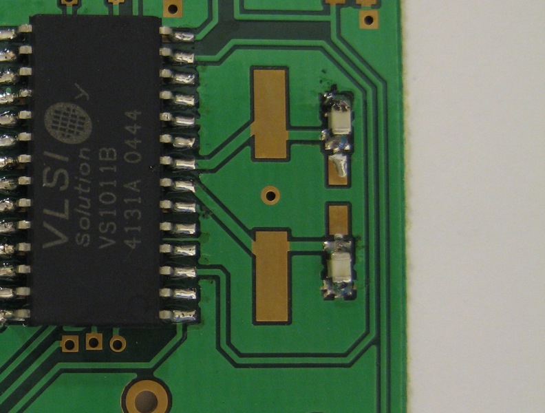
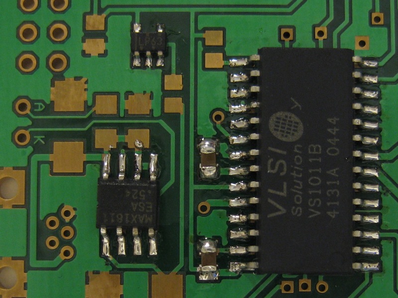
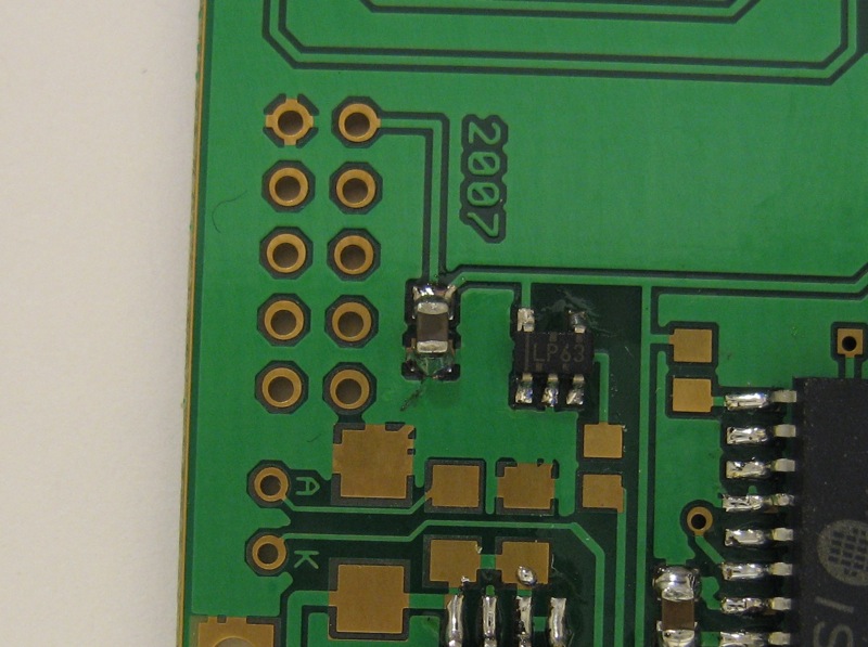
The majority of surface mount capacitors used in this project are 0805 size. I feel these are a good compromise of being small, cheap and easily available without being too difficult to solder by hand (even for someone first starting out with surface mount components at home).

These components are non-polarised so they can can go any way round on the PCB. They also have the habit of all looking the same, as they are not marked for value or tolerances as resistors might be.

The best strategy I find for dealing with these is to do each value at a time. In this project we have three values of 0805 capacitors; 0.33pF, 0.1uF, and 2.2uF. Close up views of where these capacitors are located on the PCB are shown above in images 4a-c.

The video below shows how I solder the two 0.33pF capacitors. I almost always start by tipping all the capacitors of this type and value I will need on to the PCB, manipulating them with tweezers after that. This is far easier than going back to the reel or bag after each component is done.

My approach to soldering these components (and this follows also for the resistors in step 5) is to solder one pad on the PCB first and then slide the component in while the solder on the pad is still hot. Then when the first solder joint has cooled you can solder the other side.

When using this technique you need to be careful not to move the component while the first joint cools as this will not give a reliable result. I will almost always try to use a non grounded pad for my first solder joint on the component. The grounded pad will sink a lot more heat and so will cool more slowly and thus increasing the likelihood of the component moving after you remove the soldering iron.

Its worth noting how easily I bump the PCB while soldering. To stay sane it is a good idea to secure your work before you start. The simplest way of doing this can be to place a heavy weight (such as a roll of solder) on part of the PCB to anchor it. I'm a big fan of using a drill-vice to secure a PCB as it adds weight to the board but allows you to manipulate it on your workbench. I didn't secure the work in these videos due to space limitations while filming

Another thing to note from this video is rotating the work. When soldering the second capacitor I rotate the PCB 180 degrees so the already soldered pad is on the side matching the soldering iron (On the right for me as I am right-handed). This can seemingly obvious tip can make getting into a tricky area just that much easier.

The two 0.33pF capacitors are used as part of the clock circuit that provides the 12.288MHZ clock signal for the MP3 decoding chip.

Looking at the close up photo 4a you can see that I wasn't very tidy and managed to get solder all over the adjacent pad. This is something best avoided. If it becomes a problem the excess solder can be removed using de-soldering braid or "solderwick"

The next video shows the same technique applied to the 0.1uF capacitors.

These 0.1uF capacitors are often used for "de-coupling". This means that they are used to filter out any noise in the power supply to the chip. As power tracks often have to run to all chips on a PCB, when one IC suddenly draws a lot of current it will effect the voltage and power supply of other ICs on the board. By de-coupling all the ICs using capacitors then the effects of these fluctuations can be minimised.

In this circuit C5 is used to de-couple the power supply to the VS1001 decoder. The second of the two 0.1uF capacitors, C3, is used to buffer the reference voltage on the decoder chip. When the VS1001 decodes an MP3 stream and outputs an analogue signal the voltage across C3 is used as a reference for the output. Under test conditions it is around 1.3V.

Inspecting the joins shown in photo 4b above shows large balls of solder on three out of four of the joins. This is due to using a fraction too much solder. The lowest join in the photo looks about right. Sometimes you can wick away the tiny bit of extra solder by simply reheating with a "dry" soldering iron tip. The tip will attract some of the solder but should leave enough for a good joint.

The last video in this section shows the soldering of the 2.2uF capacitor.

This capacitor, C12, is used in the power supply circuit. This capacitor is used to filter the output from the voltage regulator. This means that if the supply voltage dips suddenly the voltage to the rest of the circuit is not affected. It also means that when the circuit requires more current some of that current is drawn from the capacitor. This helps prevent any surges being passed back to the battery which could result in a brown out if the battery was unable to respond quickly enough.

Previous Next
SourceForge.net Logo Support This Project