OverviewThe following pages cover the step by step instructions on how to solder the Rev F PCB. (NOTE: The PCBs in the example pictures and videos are a prototype
version of the PCB and were mistakenly labeled Rev Ee)
Click the images to zoom in. All the construction example videos from these pages are also available on YouTube. Some good intro to soldering videos can be found at curiousinventor.com and also at sparkfun on YouTube some of the videos may be upside down on this website)
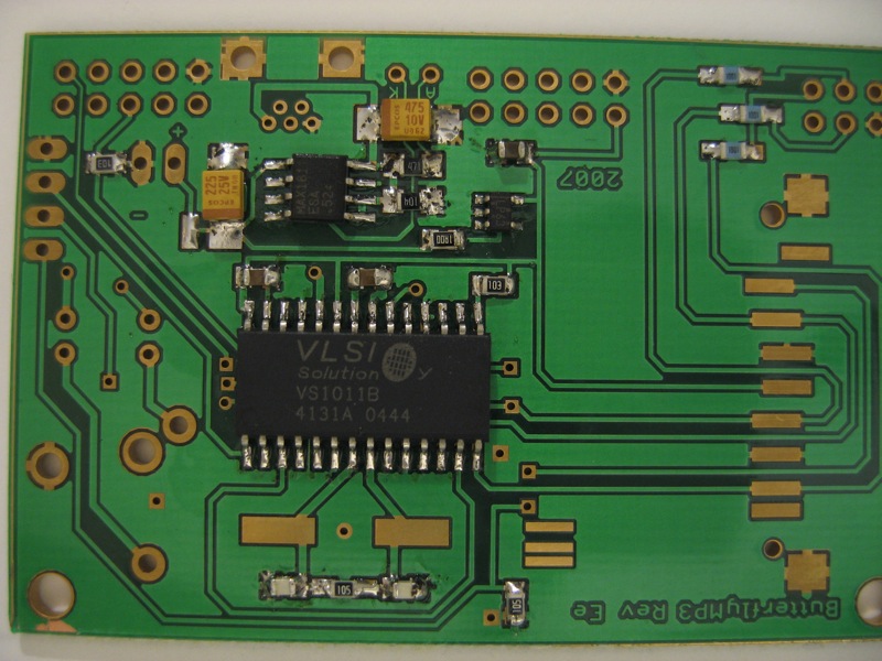
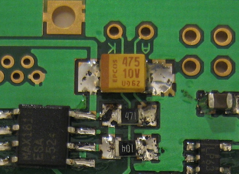
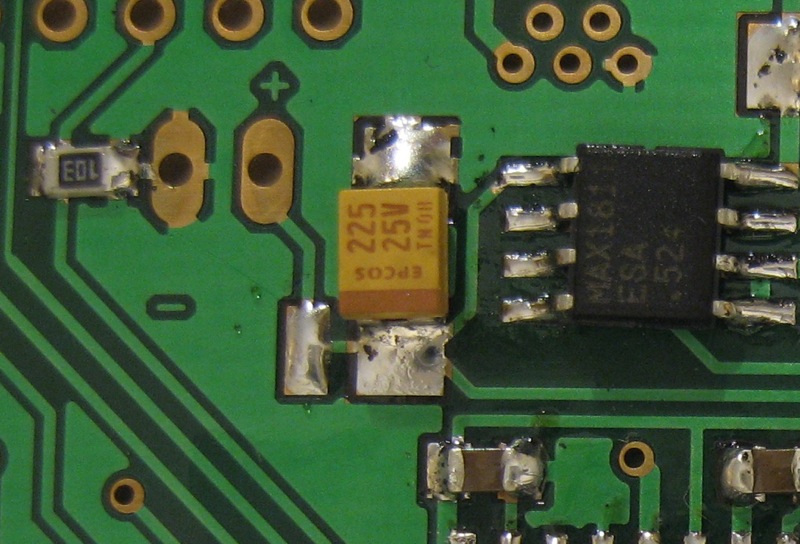
6 - C4,C7 SMD Tantalum Capacitors
The photos above show the two tantalums on the PCB. They are associated with the power input circuitry and the charging of the lithium polymer battery. C4 (photo 6b) filters the voltage from usb. It is possible for the USB line to pick up noise from the cable and any other communications going on the USB bus. This capacitor should route and noise picked up to ground and avoid it being passed into the power supply of our circuit. C7 (photo 6c) filters the voltage to the battery/ output from the max1811 charging chip. This ensures proper stability of the charging circuit. It also ensures noise from the MAX1811 charging chip does not get passed on into system. The values of 2.2uF and 4.7uF are given as nominal values by the max1811 data sheet. I have used 2.2uf for both values in the past without issue but this may mean the system is more susceptible to noise from long usb cables or cheap USB hubs. The method in the video below is the same technique used on the previous SMD components. The first step is to cover the non grounded pads of the components with solder. Once th pads have a nice even coat of solder we heat the pad and slide the capacitor into place. Note that unlike the previous capacitors and resistors in this project, tantalum capacitors are polarised. This means that the side marked with the stripe should be more positive than the other. In this case the negative side (no stripe) is connected to ground. Remember to rotate the board while soldering so you are always working from one hand to the other. Once the first pad is soldered this is a good time to check the polarity is right. As we are not soldering the ground connected pads (due to their heat sinking capacity making it difficult for the fist connection) the two ends that have been soldered should both have the stripe on. After checking they are correctly orientated return to the first capacitor and solder the remaining pad.
|