OverviewThe following pages cover the step by step instructions on how to solder the Rev F PCB. (NOTE: The PCBs in the example pictures and videos are a prototype
version of the PCB and were mistakenly labeled Rev Ee)
Click the images to zoom in. All the construction example videos from these pages are also available on YouTube. Some good intro to soldering videos can be found at curiousinventor.com and also at sparkfun on YouTube (some of the videos may be upside down on this website).
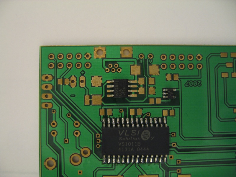
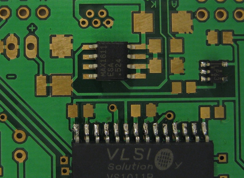
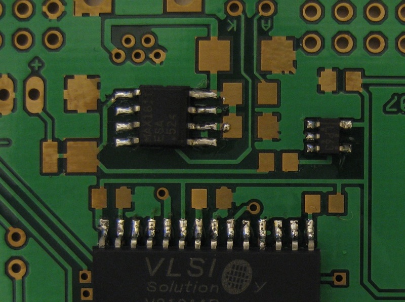
3 - U3 MAX1811 Maxim Lithium-polymer charge controller
This component is used to correctly charge the lithium Polymer battery. Fancy batteries need fancy chargers. The lithium batteries must never be charged over maximum (4.1V or 4.2v depending on manufacturer). If the voltage is very low they need to be conditioned with a lower voltage before standard charging can begin. The batteries can explode if overheated through overcharging or charging in high ambient temperatures. Luckily for us the guys at Maxim/Dallas designed a chip to take care of all of this and work from voltages supplied via USB as well as control an LED to display charging status. First check the package fits correctly on the PCB layout and note the amount of exposed copper on the pads when the component is in place. Next move the component to one side and add a small amount of solder to the fist pin to solder. I almost exclusively use the top right pin depending on how the board is orientated. The video below shows my soldering beginning with the bottom left but this video is rotated 180 degrees from my point of view. The solder is in my left hand and the iron in my right. This is a pretty good example of how not to do this. Due to having shaky hands at the time I slide the component on to the pad and heat the solder. Next I reheat the solder joint and rotate the component into place. This is generally a pretty sloppy approach and to be avoided as it often leads to pads and tracks lifting from the PCB. My original intention had been to heat the solder on the pad and slide the component across in a simple horizontal motion. After several attempts at re aligning the chip I finally get the pins in a satisfactory alignment. This can be made a lot easier if the PCB is secured down in a drill vice or even weighted down with a 500g roll of solder. Other tools that can help in this situation are tweezers or a vacuum pick up tool. Once the chip is in place a second pin is 'tacked' to fix the chips position. Next the remaining pins are soldered one by one. In an ideal example I would have soldered diagonally opposite pins so as to distribute the heat about the chip. As this is a very small chip with only 8 pins this last part of the soldering doesn't take long and so excessive heat build-up in one are is not an issue.
|