Hardware
The overall system operation is very simple. Data is read from the pushbutton
and the accelerometer and then once certain conditions are met the cell phone
motor is gently pulsed with a sine wave. Clicking the button wakes the device
and adds a stop to the alarm counter while holding the button for one second
disables the alarm and puts the device to sleep.
 Figure 1 Hardware overview.
Although the hardware design for this project was relatively simple, it was at
the limit of I/O for the tiny13 device. I set the hardware limitations so high
in this device in order to minimise production cost.
|
|
|
|
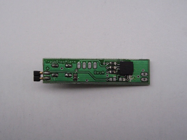
Photo 3 Although a simple PCB, soldering these packages by hand is always
a fun challenge.(click to zoom)
|
|
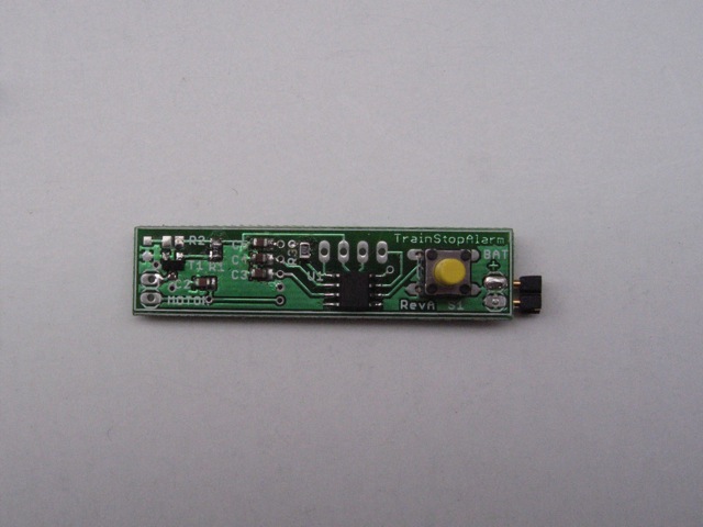
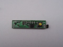
Photo 4 Top view of the PCB showing connections at each end for power and
a motor.(click to zoom)
|
In order for ISP programming to work reliably C5 must be disconnected during
programming. The circuit also has provision for an LED based visual alarm as an
alternative to the vibrating cell phone motor. In a production device the RESET
pin could be used as an IO pin to put the accelerometer into sleep mode when not
in use.
|