|
Project Page
|
|
|
| Overview | Hardware | Software | Appendix | Home |
HardwareDue to the excellent design and suitability of the AVR Butterfly module almost no modifications were needed to the board itself. In developing this application the only essential change I needed to make was the removal of a 0 ohm link resistor (R200) from the PCB. This was done to untie the timer1 input pin from the LCD colons. Using LCD pin 19 from the PCB the display is slightly corrupted when an event occurs on the T1 input. Depending on the frequency of this signal it may or may not be a problem.
A Perspex window was added to a standard aluminium enclosure to allow the LDR to function without exposure to the elements. In this photo weatherproof connectors are yet to be added to allow connection to an anemometer to measure wind speed and direction. SensorsThe current usable sensors include four analogue voltages from 0 - VCC. These are accessed on the JTAG port of the Butterfly. A 16 bit counter is available on LCD pin 19 if the modifications are made as mentioned above. In my weather station example this was connected to an anemometer that employed a magnet and reed switch to pull the signal to ground once per revolution. A 100K pull up resister was also added in this application but the internal pull up of the port could also be used. A Sensirion (www.sensirion.com) SHT75 sensor was added to the USI port on the Butterfly. The code for this could easily be adapted to support any I2C device. Using these kinds of devices adds huge range of expansion possibilities to the logger. There are also the onboard temperature, light and voltage sensors. The standard voltage reader input is wired to the battery but is simply a standard ADC channel with formatted output. DS18B20Firmware version 0.27 and above supports the use of DS18B20 1-Wire sensors from Dallas-Maxim. (info) The compiler will produce the smallest code for a single sensor as 1-Wire search routines can be ommitted, but is compatible with multiple sensors on a single 1-Wire bus. I have tested this with only 2 sensors at a time but the code should work with more. The firmware does not set the resolution and assumes the default 12 bit resolution is selected on the devices. The conversion time is 750ms with 12Bit resolution. If multiple sensors are being used the time is 750ms per device as the read routine is called repeatedly for each device. When the device is powered on the 1-Wire bus is scanned for sensors. If there are less sensors found than configured in the source code at compile time then the unused sensors are logged as -0.00 degrees. The 1-wire code is based on code by Martin Thomas found here. I have simply stripped out code that wasn't needed for basic use of the sensors to save space in the butterfly. J/K-Type Thermocouple (MAX6675)Firmware version 0.30 and above support the use of J and K type thermocouples with the MAX6675 chip from Maxim. (info) The library has configurable support for averaging readings but each reading takes 200ms so an 8 point average will take 1.6s to complete. If you use multiple reading averaging please make sure that your logging interval is long enough to ensure enough time for the complete reading to finish. While thermocouples are capable of measuring wide ranges of temperature both positive and negative the MAX6675 is limited to returning readings between 0°C and +1024°C. If the chip detects an open thermocouple then the system will log '-1' as the temperature. The MAX6675 connects to the AVR Butterfly via the SPI bus. This bus is also used by the onboard Dataflash and the Kionix accelleration sensors (when in use). As this bus is already available the only additional pins required is a single chip select (CS). The library curently only supports a single thermocouple but the code could easily be expanded to suport multiple MAX6675s requiring a single CS line for each additional chip and thermocouple. The SPI Bus is available on PORTB and via the ISP connector. An example breakout PCB for the MAX6675 is published here Default wiring from the brokentoaster.com MAX6675 PCB to the AVR Butterfly Logger is given below:
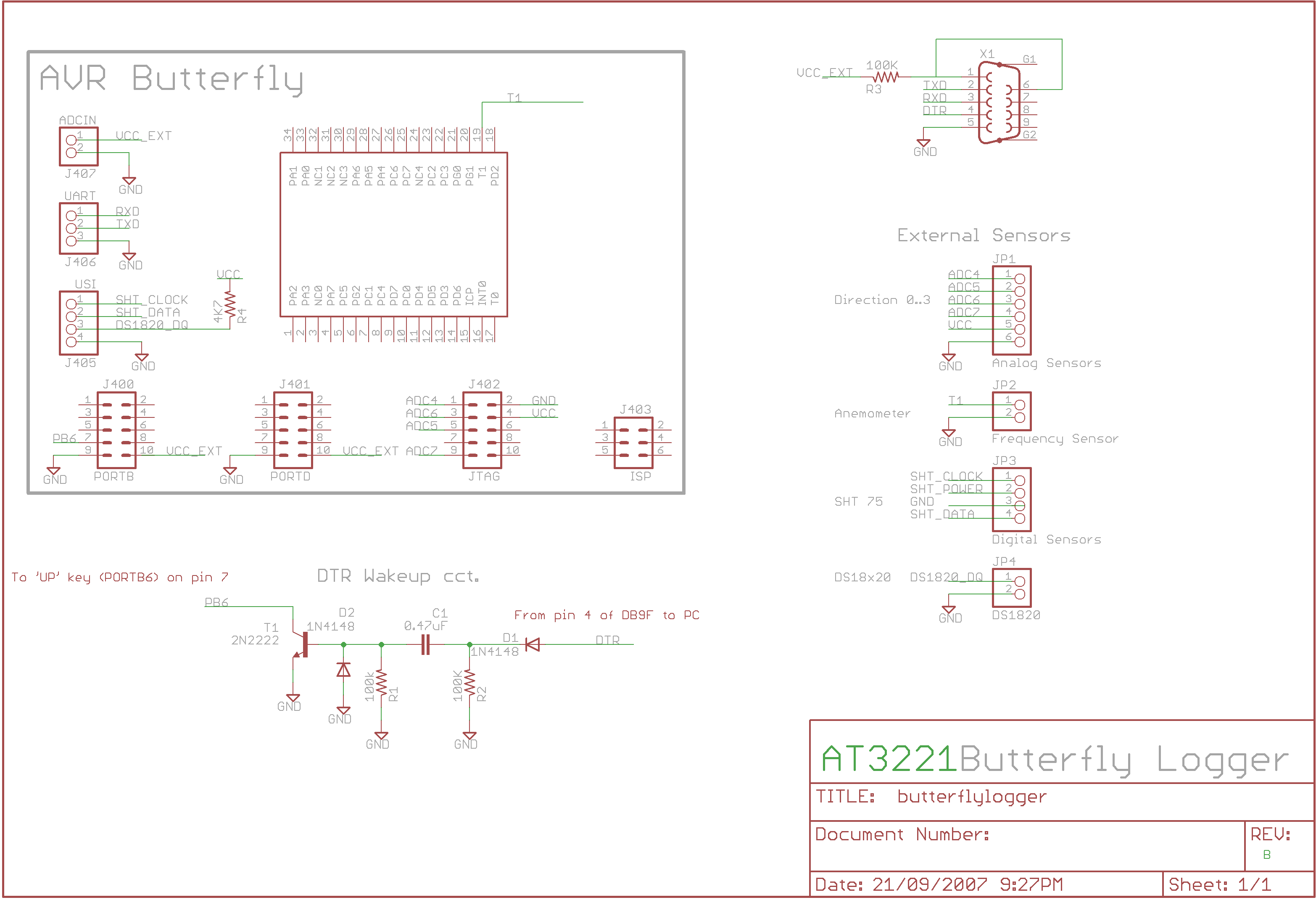
Redundant PowerA very simple redundant power system is available on the AVR Butterfly. The onboard coin cell and external power input are connected to VCC via two diodes. As well as offering polarity protection this allows the system to select which ever power source has the greatest voltage. Three AA batteries are used as part of the redundant power system in the system shown in the Photo above. Should these batteries fail (expected life in this application is over 12 months) the coin cell supplied with the butterfly will take over. Although the button cell does allow the system to remain powered up when the external battaries fail, it does not ensure reliable writing to the flash. Thanks to Raul for reminding me. Wake-up CircuitryAn important part of a data logger application is power consumption. This device takes full advantage of the AVRs power saving mode to disable as many clocks as possible when not needed. One problem found was that in order to achieve maximum power savings the USART needed to be shut down. This meant that in order to check the device status or to download data we needed to physically go over and poke the joystick up. Although not a big issue for those situations where it's sitting on your workbench measuring the temperature of a cup of coffee it becomes problematic when the device was strapped to a cell phone and left to rust in a secluded orchard. The solution was a simple circuit to pulse the joystick signal and emulate a quick click of the joystick when the DTR signal from the serial connection was activated. The circuit is easily constructed from discrete components and the schematic is shown in Appendix A. The battery voltage is applied to pins 1 and 6 of the 9-pin D connector to allow the battery voltage to be checked quickly and to allow three-wire serial cables with these pins connected to the DTR signal to function correctly.
|